 [email protected]
|
[email protected]
|
 530-666-6700
 .jpg)

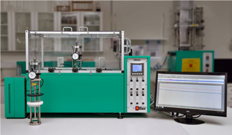 Relaxation System for continuous measurement in either tension or compression
Continuous stress relaxation testing |
Discontinuous stress relaxation testing |
| Less manual work, measurement will continue throughout the test after it is started. | More manual work, needed to manually perform the measurements at certain points during the test period. |
| Logging automatically and continuously which means that if wanted, it is possible to obtain measured values from any given point from the test after the test is terminated. | No extra data is saved, only the manual taken measurements. Not possible to add extra evaluation points after the test is finalized. |
| No physical movement of the rigs after the test is started. | It has been shown that each time a rig is moved the result may be affected due to the vibration that occurs in this operation. |
| Most of Elastocon’s customers around the world ask for this type of testing, several big companies have it in their company standard. | Less customers ask for this type of test, it is included in the internal standards of some large companies. |
| Possible to run tests automatically according to ISO 3384-1, ISO 3384-2 as well as ISO 6914 and other technically equivalent standards. | No automatic testing is possible, requires a lot of manual work. But testing according to ISO 3384-1 and 3384-2 is possible of course. |
| Possible to run tests automatically with either stable or cyclic temperatures. | The temperature will not be stable throughout the whole test, the measurements will, as default, take place in ambient room temperature (can also be done within a special temperature chamber). |
| Test either in compression or tension, in air/gases or liquid. | Test in compression, air or liquid (liquid might be rather messy during the measurements). |
| Automatic testing according to ISO 3384-1 method B with a programmable oven. | |
| Cycling testing according to ISO 3384-2 in temperature interval -40 to +250 °C |

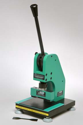
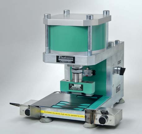
Specimen Cutting Press |
EP 02 |
EP 08 |
| Cutting pressure, kN | 18, max 25 | 10 |
| Air pressure, Bar | 6, max 8 | – |
| Stroke, mm | 25 | 20 |
| Height adjustment, mm | 50 | 30 |
| Cutting die height, mm | 25 – 65 | 30 – 60 |
| Base Plate size,mm | 200 x 200 | 200 x 150 |
| Dimensions w x d x h, mm | 360 x 420 x 400 | 215 x 265 x 525 |
| Weight, kg | 62 | 19 |
| Material | aluminium and zinc coated steel | aluminium and painted steel |
| Safety | 2-hand operation | safety stop |

|
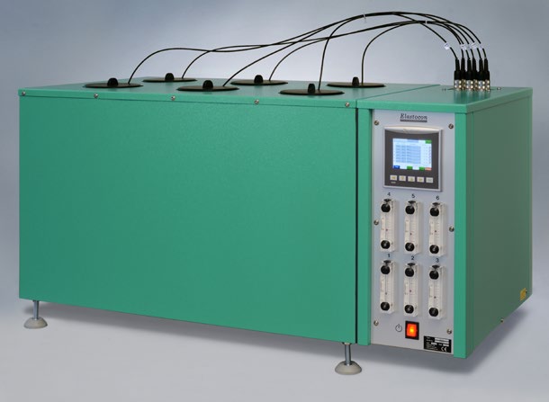
EB 19 |
EB 20 |
|
|
Temperature range, °C: |
+40 to +200 |
+40 to +200 |
|
HT-version, °C: |
+40 to +300 |
+40 to +300 |
|
Temp. control, +40 to +100 °C, °C: |
± 0,5 |
± 0,5 |
|
+101 to +200 °C, °C: |
± 1,0 |
± 1,0 |
|
+201 to +300 °C, °C: |
± 1,5 |
± 1,5 |
|
Temp. variation in time,°C: |
± 0,25 |
± 0,25 |
|
Temp. variation in space, %: |
± 0,5 |
± 0,5 |
|
Temperature sensors: |
Pt 100, 1/3 DIN |
Pt 100, 1/3 DIN |
|
No. of temperatures: |
4 |
6 |
|
No. of cells: |
4 |
6 |
|
Air speed, m/s: |
<0,002 |
<0,002 |
|
Air changes, changes/hour: |
3 to 20 |
3 to 20 |
|
Useful volume, l: |
4 × 2,4 |
6 × 2,4 |
|
Dimensions, inner, dia × h, mm: |
100 × 300 |
100 × 300 |
|
Dimensions, external, w × h × d, mm: |
760 × 500 × 510 |
960 × 500 × 510 |
|
Weight, kg: |
55 |
74 |
|
Voltage, V/phase/freq: |
220–240/1/50 (110–120/1/60) |
220–240/1/50 (110–120/1/60) |
|
Power, W: |
900 |
1300 |
|
Standards: |
ISO 188 method A, IEC 60811-401, IEC 60216-4-3, DIN 53508 p. 6.4 |
ISO 188 method A, IEC 60811-401, IEC 60216-4-3, DIN 53508 p. 6.4 |

| Temperature range, °C: | EB 11-II +40 to +200 |
EB 28HT +40 to +300 |
||||||||||||||||||||||||
| Temp. control, | ||||||||||||||||||||||||||
| +40 to +100 °C, °C: | ± 1,0 | ± 1,0 | ||||||||||||||||||||||||
| +101 to +200 °C, °C: | ± 2,0 | ± 2,0 | ||||||||||||||||||||||||
| +201 to +300 °C, °C: | ± 3,0 | |||||||||||||||||||||||||
| Temp.variation in time,°C: | ± 0,5 | ± 0,5 | ||||||||||||||||||||||||
| Temp.variation in space, %: | ± 0,5 | ± 0,5 | ||||||||||||||||||||||||
| Temperature sensors: | Pt 100, 1/3 DIN | Pt 100, 1/3 DIN | ||||||||||||||||||||||||
| No. of temperatures: | 1 | 4 | ||||||||||||||||||||||||
| Test Tubes: | 24 | 4 x 6 | ||||||||||||||||||||||||
| dia x h, mm: | 38 x 300 | 38 x 300 | ||||||||||||||||||||||||
| Dimensions, external, | ||||||||||||||||||||||||||
| w x h x d, mm: | 760 x 820 x 510 | 760 x 820 x 510 | ||||||||||||||||||||||||
| Weight, kg: | 88 | 70 | ||||||||||||||||||||||||
| Voltage, V/phase/freq: | 220–240/1/50 | 220–240/1/50 | ||||||||||||||||||||||||
| (110–120/1/60) | (110–120/1/60) | |||||||||||||||||||||||||
| Power, W: | 900 | 900 | ||||||||||||||||||||||||
| Connections: | – | – | ||||||||||||||||||||||||
| Standards: | ASTM D865, | ASTM D865, | ||||||||||||||||||||||||
| ASTM D471, | ASTM D471, | |||||||||||||||||||||||||
| ISO 1817 | ISO 1817 | |||||||||||||||||||||||||


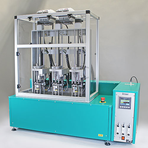
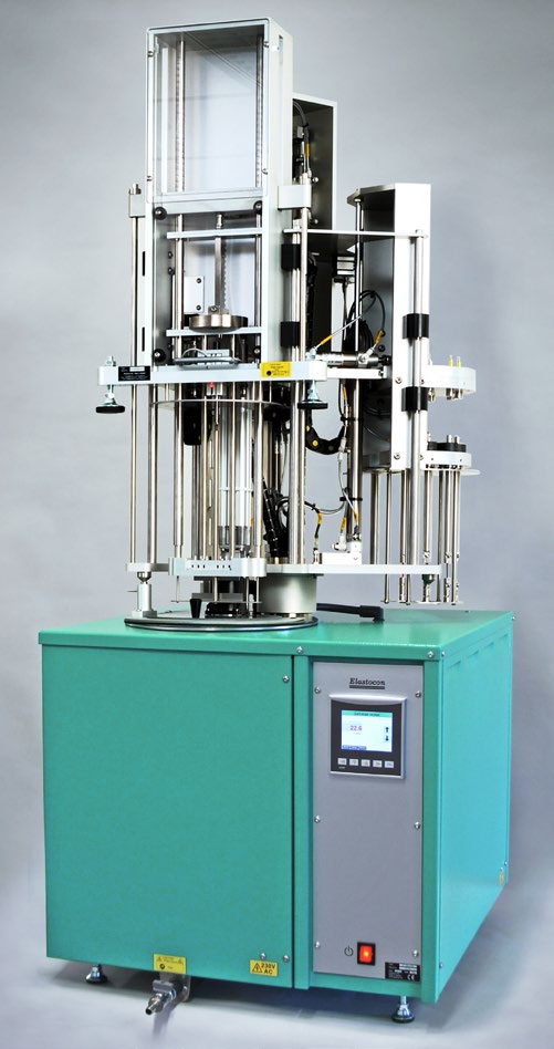
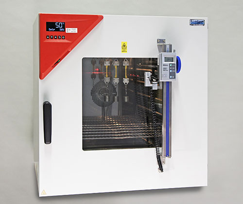
Elastocon offers two models for high precision automatic relaxation and creep tests, EB 18 II 3 and EB 32. Both models perform tests according to ISO 188 method A, ISO 3384-1 method A, and method B for EB 32, ISO 6914 method A and ISO 899 with modified test specimen (no strain gauge required).
In EB 18II3, each test station can run with an individual temperature, between +40 °C to +200 °C. The EB 32 is equipped with a liquid circulator (EB 32.01) for cooling, and can cycle between -40 °C and +200 °C, with the same temperature in all test stations, thus also performing tests according to ISO 33841 method B and ISO 33842.

Common specifications
• The oven performs well inside the apparatus requirements in ISO 188, IEC 811 and other equivalent standards.
• Special design with controlled air exchange rate and low air speed.
• The casing consists of steel, painted with epoxy powder paint in bluegreen colour.
• The inner chamber is made of stainless steel.
• Temperature controller with 0,1°C setpoint.
• Solid state relay for safe control.
• Temperature indicator with sensor in the inner chamber.
• Fixed over temperature fuse.
• Fixed set air exchange rate 7 or 14 changes per hour, preset by manufacturer.
• The air speed is low and is dependent on the air exchange rate only.
• Cooling channels in the casing for low surface temperature.
• Controlled cooling fan for the electronics cabinet.
• Run-time meter.
• Countdown timer.
• Door sensor to turn off laser and illumination when the door is opened.


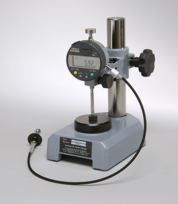
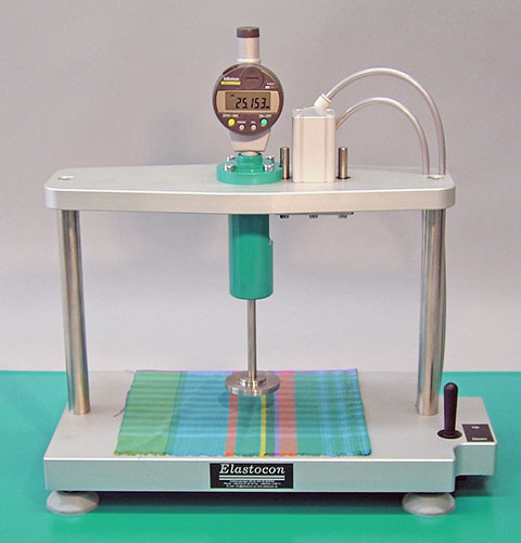
The EV 01 Thickness Gauge is intended for rubber or plastic thickness measurement according to ISO 23529 and compression set measurement according to ISO 815.
| Article number | Use | Resolution [mm] | Accuracy [mm] | Foot Pressure* [kPa] | Foot size* [mm in diameter] |
Range [mm] |
| EV 01B | Rubber and plastic samples | 0,001 | ±0,003 | 22 | 4,3 | 12 |
| EV 01F | Thin samples, such as condoms and plastic films | 0,001 | ±0,003 | 22 | 10 | 12 |
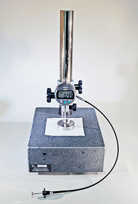
The EV 06 Thickness Gauge is intended for textile thickness measurement according to ISO 5084. Available in two versions: EV 06A 0,1 and EV 06B.
| Article number | Use | Resolution [mm] | Accuracy [mm] | Foot Pressure* [kPa] | Foot size* [mm in diameter] |
Range [mm] |
| EV 06A 0,1 | Textile samples | 0,01 | ±0,03 | 0,1 | 50,5 | 12 |
| EV 06B | Textile samples | 0,001 | ±0,005 | 0,5 or 1 | 50,5 | 12 |
The EV 07B Pneumatic Thickness Gauge is intended for textile thickness measurement according to ISO 5084.
| Article number | Use | Resolution [mm] | Accuracy [mm] | Foot Pressure* [kPa] | Foot size* [mm in diameter] |
Range [mm] |
| EV 07B | Pneumatic, for textile samples | 0,001 | ±0,005 | 1 | 50,5 | 25 |

Hot set testing of cable materials is an easy way to determine if the material used in the insulation or sheathing of cables is sufficiently cross-linked. Crosslinking increases the bonding between the polymer chains in a material. The purpose of crosslinked insulation and outer sheath materials is usually to improve the mechanical and electrical properties.
We offer two instruments for hot set testing of cable materials: EB 16-II hot set tester and EB 30 hot set oven basic.
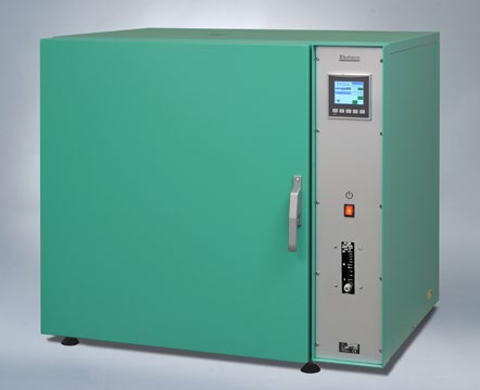
The EB 16-II hot set tester is made for hot set testing of cable material according to IEC 60811-2-1 and other equivalent standards.
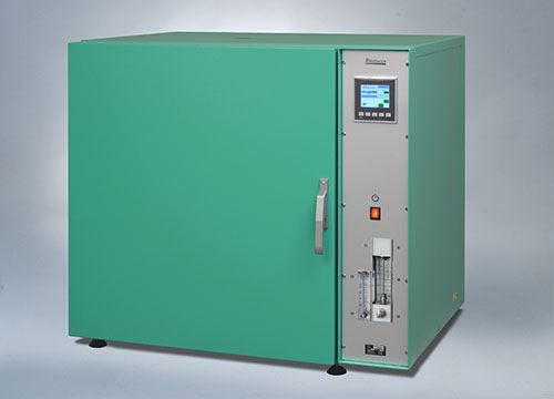
The basic EB 30HT hot set oven is made for hot set testing of cable material according to IEC 60811-507 and technically equivalent standards.

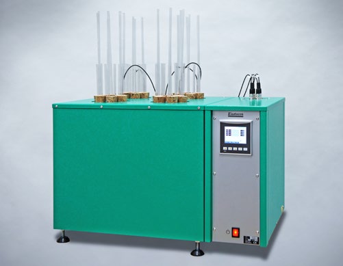
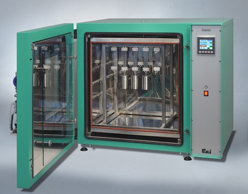
The EB 38 high temperature cell oven for relaxation tests has 4 cells with individual temperatures and individual control of the air exchange rate for each cell. The temperature range is +40 °C to +350 °C.
The EB 38 cell oven is specially designed for stress relaxation tests. This means that the inner height of the cells are adapted to fit our relaxation rigs to achieve as good thermal contact as possible with the bottom of the cell.
The oven also has an integrated draught hood that eliminates the changes in the force during the test due to temperature changes in the environment around the top part of the rigs. The hood is made of polycarbonate, and has a temperature control system (Peltier cooling system) capable of keeping the temperature within ± 0,25 °C.
Note: For the best performance of the instrument, we recommend a placement in an environment with a stable temperature between +10 to +30 °C.
+40 °C to +350 °C
 Updating…